As a temperature controller supplier who’s spent the last 12 years troubleshooting wiring issues for HVAC, refrigeration, and commercial cold storage clients, I’ve lost count of how many field service calls start the same way: “I bought a compressor and a temperature controller, followed the basic diagram online, and now neither works.” Most of the time, the problem isn’t a faulty part—it’s a missed wiring detail that separates a safe, reliable installation from a fire hazard or damaged equipment. Today, I’m breaking down how to wire a temperature controller to a compressor correctly, with step-by-step guidance, common mistakes to avoid, and tips from my team of in-field technicians who troubleshoot these setups every week. Temperature Controller
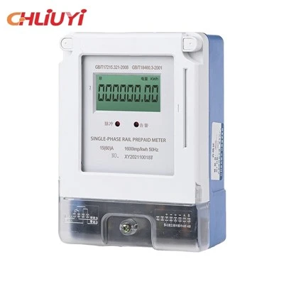
First, let’s ground this in what you’re actually working with. Temperature controllers (the ones we supply, specifically, are designed for on/off load control, which is what most small to medium compressors use, like those in walk-in freezers, residential HVAC systems, and commercial coolers) regulate compressor operation by turning it on when temperature rises above a set point and off when it drops below. Compressors, by contrast, are high-load devices that draw 5 to 15 times their rated current on startup, and they require a dedicated circuit path to avoid frying the controller’s sensitive low-voltage logic.
Before you touch any wires, pause to prep the components you’ll need—skipping this step is how half the errors start. First, confirm your temperature controller has the right relay rating for your compressor. Our entry-level digital controllers, for example, have a 15A relay output at 120VAC, which works for most 1HP compressors, but 2HP and larger compressors will need a contactor (a separate electromechanical switch that handles the high compressor load, since the controller’s relay isn’t built to handle that startup current). You’ll also need basic tools: a flathead screwdriver, Phillips head, wire strippers, a multimeter (non-negotiable for checking voltage), heat shrink tubing or electrical tape, and wire nuts for connecting circuits. And critical: turn off the main power to the compressor and controller before doing any wiring. I can’t stress that enough—two of our technicians last year had to be pulled from small burns because they skipped this step on a last-minute job.
Let’s walk through the wiring process step by step, starting with low-voltage connections, since that’s where the controller’s temperature sensing happens. First, locate the sensor terminals on your temperature controller. These are almost always labeled “S1” and “S2,” and they’re for the temperature probe (usually a thermistor, which we supply as a standard part with every controller order). Strip ¼ inch of insulation from the end of the probe’s two wires, then insert them into the S1 and S2 terminals, tightening the screws firmly—loose connections here cause the controller to read the wrong temperature, so test with your multimeter to confirm a secure connection. Next, set your temperature set point and differential on the controller’s display. The set point is the temperature you want (e.g., 35°F for a walk-in cooler), and the differential is how far the temperature must drop before the compressor turns off (usually 2 to 5°F, to prevent short cycling the compressor, which wears it out fast). For example, if your set point is 35°F and differential is 3°F, the compressor will turn on at 38°F and off at 35°F. That’s a good range to start with, but adjust based on your specific cooling needs.
Now move to the line-voltage connections, which is where most people mess up. There are two wiring setups depending on whether your compressor is low-voltage (120V) or line-voltage (240V, common for larger compressors). Let’s start with the most common: 120V compressor with a controller that doesn’t need a contactor first. Locate the “L” (line power) and “N” (neutral) terminals on your controller, plus the “COM” (common), “NO” (normally open), and “NC” (normally closed) terminals on the controller’s relay output. Here’s the correct order: First, connect the main line power (from your breaker box) to the “L” terminal on the controller, and the neutral wire to the “N” terminal. Next, take a wire from the “NO” terminal (this is the switch that closes when the controller calls for cooling) to the “common” terminal on the compressor’s contactor or motor terminal block. Then, take another wire from the compressor’s “hot” power input (the one that turns it on) to a separate breaker in your panel rated for the compressor’s current. Wait—no, let’s make that clearer for beginners: The compressor’s power supply always comes from its own dedicated breaker, not the same as the controller. The controller acts as a switch between the main power and the compressor’s high load. If you’re working with a 240V compressor (the same as for large window AC units or walk-in freezers), the wiring is almost identical, except you’ll use two hot wires (no neutral) from a 240V breaker instead of the L and N.
Now, when do you need a contactor? This is the most common question we get from customers: If your compressor is over 1HP (120V) or 2HP (240V), or if your controller’s relay is rated for less than 20A, a contactor is non-negotiable. A contactor is a separate device that has a small coil (rated for 120V, usually) and two large power terminals for the compressor. The controller’s relay switches the contactor’s coil, which in turn switches the full compressor load—this protects the controller’s relay from burning out, which is a huge warranty issue we see all the time when customers skip the contactor. The wiring for a contactor setup adds two simple steps: instead of connecting the controller’s NO terminal directly to the compressor, connect the controller’s NO and COM terminals to the contactor’s coil terminals (labeled “A1” and “A2”). Then, connect the main 240V power to the contactor’s L1 and L2 terminals, and the wires going to the compressor to the contactor’s T1 and T2 terminals. That’s it—everything else stays the same.
Now, let’s go over the most common mistakes we see, because even if you follow the diagram, these will break your setup. First, wiring the sensor backwards: the thermistor probe is polarized, so if you swap S1 and S2, the controller will read temperatures that are 20°F too high or too low, so the compressor will run constantly or never turn on. Always check the probe’s label—we print small arrows on the probe’s jacket to indicate which wire goes to which terminal. Second, short cycling the compressor: that’s when the compressor turns on and off every few minutes instead of running for at least 10 minutes. That happens when your differential is too small (less than 2°F) or the wiring has a loose connection that makes the controller sense temperature fluctuations. Third, using undersized wire for the compressor: compressors draw high startup current, so if you use 14-gauge wire for a 2HP compressor, it will overheat and cause a fire. Always use 12-gauge wire for 2HP 240V compressors, 10-gauge for 3HP and up. Fourth, not turning off power: I’ve had three customers this year who did the wiring with power on, and ruined both the controller and the compressor—even a small jolt from a 120V line can fry the controller’s logic board, which is not covered under warranty.
Once you’ve finished wiring, test the setup to make sure it works correctly. Turn the main power on, then adjust the controller’s set point 5°F above room temperature—you should hear the contactor click (if you’re using one) and the compressor should start running within 10 seconds. Wait a few minutes, then adjust the set point 5°F below room temperature— the compressor should turn off. If it doesn’t turn on, use your multimeter to check if you have power at the “L” terminal of the controller, then check the output from the NO terminal when the set point is above room temperature. If the compressor runs constantly, even when the set point is below room temperature, the most likely issue is a bad sensor probe or a reversed sensor wire. If the contactor chatters (makes a rapid clicking noise), that’s a loose connection on the coil terminals, so tighten those screws.
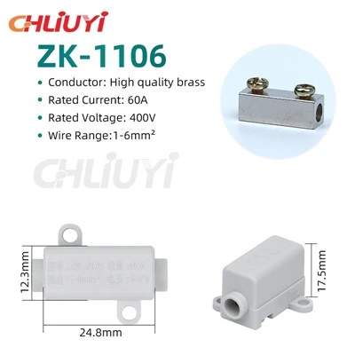
As a temperature controller supplier, my team and I know that even the best controller won’t work if it’s wired incorrectly. We work with installers and do-it-yourselfers every day to troubleshoot wiring issues, and we’re here to help you make sure your setup is safe and reliable. If you’re working on a large-scale project, have questions about matching a controller to your compressor, or need guidance on custom wiring for a specific application, reach out to our team to discuss your needs. We offer pre-wired kits for small compressors, technical support for field installations, and customized controllers for commercial refrigeration and HVAC systems. Don’t risk damaging your equipment or compromising your cooling—let us help you get the wiring right the first time.
Energy Meter References
- American Society of Heating, Refrigerating and Air-Conditioning Engineers (ASHRAE), Refrigeration and Safety Standards for Commercial Compressors, 2021
- National Electrical Code (NEC), Article 440: Air-Conditioning and Refrigeration Equipment, 2023
- U.S. Department of Energy, Guide to Correct Wiring for Temperature Control Systems, 2022
- International Electrotechnical Commission (IEC), Standard for Low-Voltage Control Devices, 2020
Zhejiang Liuyi Electrical Technology Co., Ltd.
Zhejiang Liuyi Electrical Technology Co., Ltd. is one of the most professional temperature controller manufacturers and suppliers in China. We have world-leading production equipment and strong manufacturing capabilities. Please rest assured to wholesale high quality temperature controller made in China here from our factory. Customized orders are welcome.
Address: No. 16 Zhengshun East Road, Xiangyang Industrial Zone, Liushi Town, Leqing City, Wenzhou City, Zhejiang Province
E-mail: hazel@chliuyiele.com
WebSite: https://www.chliuyiele.com/
